
FSE 450 SM - Off-road motorcycle GAS GAS - Free user manual and instructions
Find the device manual for free FSE 450 SM GAS GAS in PDF.
User questions about FSE 450 SM GAS GAS
0 question about this device. Answer the ones you know or ask your own.
Ask a new question about this device
Download the instructions for your Off-road motorcycle in PDF format for free! Find your manual FSE 450 SM - GAS GAS and take your electronic device back in hand. On this page are published all the documents necessary for the use of your device. FSE 450 SM by GAS GAS.
USER MANUAL FSE 450 SM GAS GAS
GAS GAS thanks you for your confidence.
By choosing the new GAS GAS FSE / FSE SM 2005 you have just entered the great GAS GAS family and, as a user of the number one off-road motorbike manufacturer, you deserve the distinguished treatment that we wish to offer to you both in our after-sale relationship and in the explanations that we provide in this manual.
Our FSE / FSE SM 2005 is a bike conceived for highly competitive performance. In fact this bike is the fruit of many years of competition and experimentation in these demanding disciplines; many great trial riders have contributed their expertise and achievements to the essential data we have used to create these high-quality, exclusive motorcycles incorporating key features such as reliability, high performance and stability.
Congratulations for making, without a doubt, the right choice. With skill at the controls of this motorbike, an adequate preparation and the corresponding essential servicing this GAS GAS will remain highly reliable and you will be able to enjoy the most comfortable and rewarding motor sport.
Thank you for your confidence and welcome to GAS GAS motos SA.
IMPORTANT NOTICE
Read this manual carefully. This manual covers aspects that will contribute to your security and to that of others, as well as guaranteeing a correct conservation and maintenance of this GAS GAS motorcycle you have just acquired.
All of the instructions to correctly handle and drive this motorcycle are described in detail. Each message will be preceded by a symbol.
WARNING
This warning symbol identifies special instructions or procedures that, if not correctly followed, could result in personal injury, or even death.
CAUTION
This caution symbol identifies special instructions or procedures that, if not strictly observed, could result in damage to or destruction of equipment.
NOTE
This symbol indicates points of particular interest for more efficient and convenient operation.
Inadequate driving skill could cause problems to the environment and conflict with other people. Responsible use of your motorcycle will ensure that these problems and conflicts do not occur.
TO PROTECT THE FUTURE OF YOUR SPORT, MAKE SURE YOU USE YOUR BIKE LEGALLY, WITH CONCERN FOR THE ENVIRONMENT, AND RESPECT THE RIGHTS OF OTHER PEOPLE.
Motorcycle riding is a fantastic sport, and we hope you will enjoy it to the fullest.

OIL RECOMMENDED:

TABLE OF CONTENTS
Foreword 3
Important notice 4
Table of contents 5
General information 6
Component locations 8
Side stand 10
Petrol 10
Serial number and the qualification approval plate. 11
Starting and stopping the engine 12
Cold starting 13
Gear changes. 13
Stopping the motorcycle. 14
Break-in 14
Maintenance chart 15
Battery 16
Cooling system 17
Spark plug. 20
Air filter 23
Accelerator cable. 24
Clutch. 25
Exhaust system 25
Chain guide 26
Tension adjustment 27
Handle bars. 29
Brakes 29
Steering 31
Steering lock 32
Front forks. 33
Rear suspension 36
Wheels 38
Cleaning 39
Tighten bolts and nuts 40
Tightening torque table 41
Lubrication 42
Engine oil. 43
Suspension adjustment. 47
In competition. 52
Storage 53
Multi-function instructions 53
Fault diagnosis 55
Electrical schemas 61
Guarantee manual 63
GENERAL INFORMATION
| ENGINE | |
| Engine | 4 stroke, single-cylinder DOHC 4 valves, liquid cooled |
| Displacement in cubic centimetres | 443 cc |
| Bore and stroke | 95 x 62.6 mm. |
| Spark plug | NGK CR8E or DENSO U24ESR-N |
| Fuel supply | Magneti Marelli electronic injection |
| TRANSMISSION | ||
| Transmission type | 6 speed | |
| Clutch type | Oil bath, multi-disk hydraulic action | |
| Secondary transmission | By chain | |
| Gear ratio | 1st 2.071(29/14) | |
| 2nd 1.625(26/16) | ||
| 3rd 1.333(24/18) | ||
| 4th 1.100(22/20) | ||
| 5th 0.913(21/23) | ||
| 6th 0.791(19/24) | ||
| Primary reduction ratio | 2.85(57/20) | |
| Final reduction ratio | 3.692 (48/13) | |
| Overall drive ratio | 8.149(6th gear) | |
| Transmission oil | Capacity | 1200 cc |
| Type | 5W40 API SF or SG | |
| CHASSIS | ||
| Type | DELTABOX, semi double cradle chassis made from rectangular Cromoly tubes. Aluminium rocker | |
| Tyre sizes | Front | FSE - 90/90 x 21 |
| FSE SM - 120/60 ZR17 | ||
| Rear | FSE - 140/80 x 18 | |
| FSE SM - 150/60 ZR17 | ||
| Suspension | Front | Öhlin sø 48mm inverted fork. |
| Marzocchiø 45mm inverted fork. | ||
| Suspension stroke | Rear | Progressive system with single multi-adjustment ÖHLINS shock absorber. |
| Front | 295 mm. | |
| Rear | 320 mm. | |
| Front suspension oil | MARZOCCHI SAE 7.5 | |
| ÖHLINS SAE 5 - 7.5 | ||
| Front fork oil level | Marzocchi: 110 mm (compressed, without spring). | |
| ÖHLINS: 110 mm (compressed, without spring). | ||
| BRAKES | ||
| Type | Front / rear | Disk brakes, NISSIN pump and simple / double callipers. |
| Effective disk diameter | Front | 260 mm |
| Rear | 220 mm | |
| DIMENSIONS | |
| Overall height | 1260 mm. |
| Overall length | 2135 mm. |
| Overall width | 810 mm. |
| Wheel base | 1475 mm. |
| Minimum ground clearance | 340 mm. |
| Fuel tank capacity | 9.5 litres |
| Weight | 119 Kg. |
(Specifications subject to change without notification, also possibly not applicable in some countries).
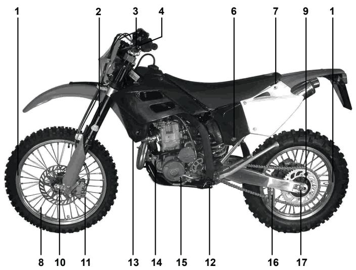
1- Clutch handle
2- Engine start button
3-Fuel tank cap
4- Front brake fluid tank
5- Front brake handle
6-Throttle control
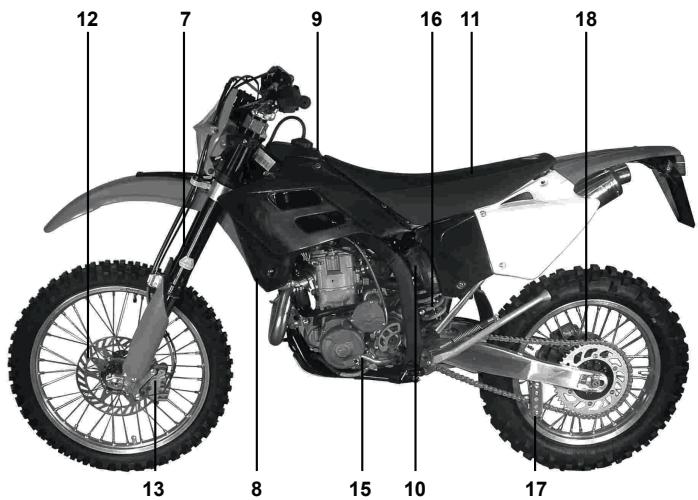
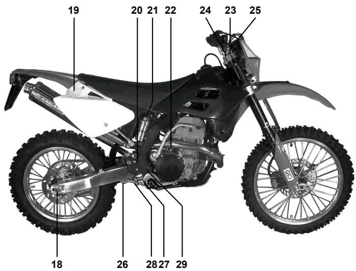
GAS GAS FSE SM 450
1- Clutch handle
2- Engine start button
3-Fuel tank cap
4- Front brake fluid tank
5- Front brake handle
6-Throttle control
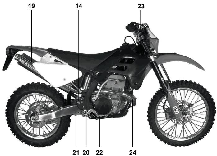
7- Front suspension
8-Radiator
9-Fuel tank
10-Air filter
11-Seat
12- Front brake disk
13- Front brake callipers
14- Rear brake fluid tank
15-Shift pedal
16- Rear shock absorber
17-Chain guide
18-Chain
19-Silencer
20- Rear shock absorber gas tank
21-Tie rod and rocker suspension
22-Rear brake pedal
23- Engine oil rod
24- Exhaust bend
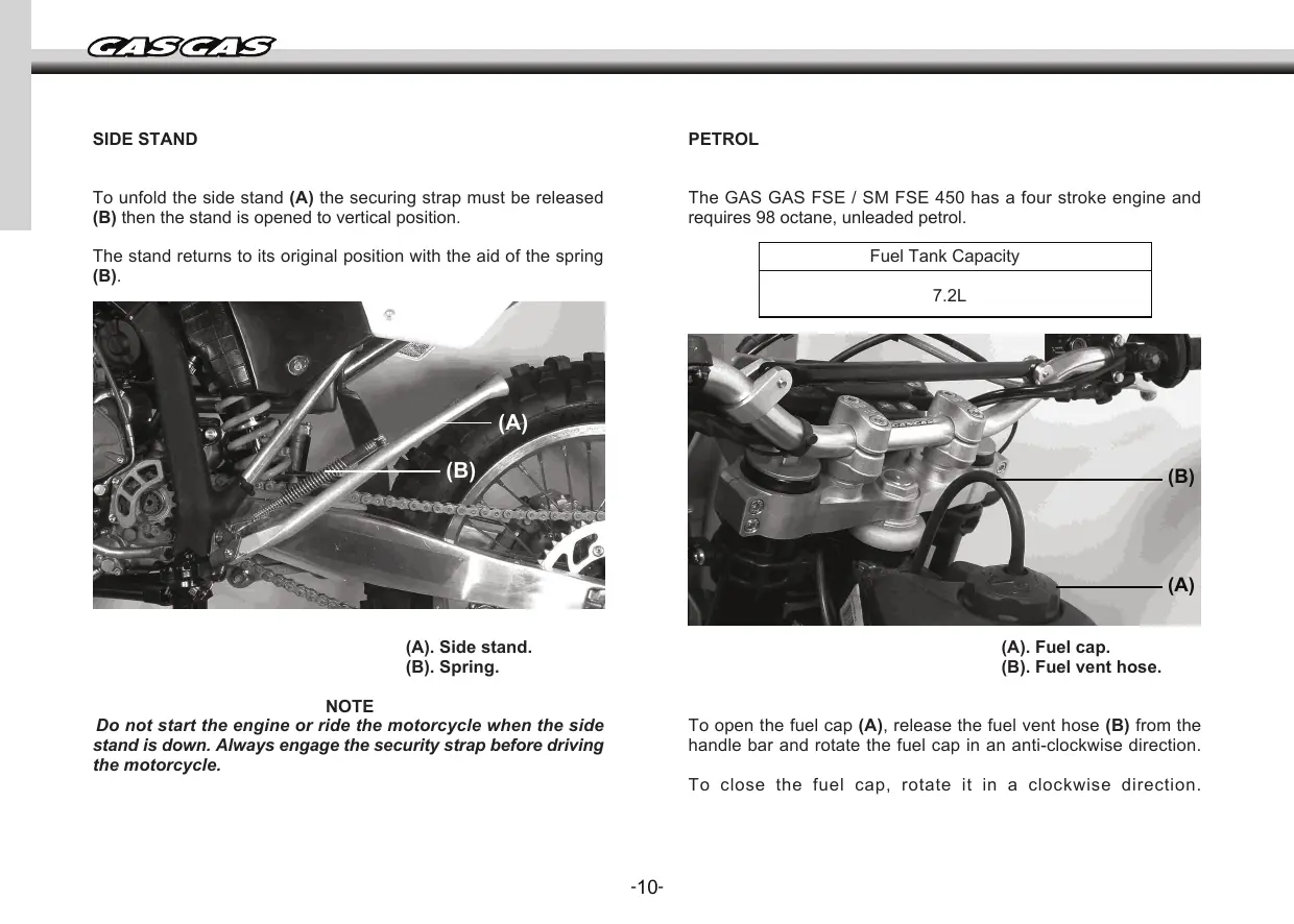
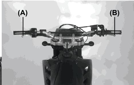
SIDE STAND
To unfold the side stand (A) the securing strap must be released (B) then the stand is opened to vertical position.
The stand returns to its original position with the aid of the spring (B).
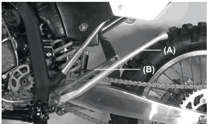
(A). Side stand.
(B). Spring.
NOTE
Do not start the engine or ride the motorcycle when the side stand is down. Always engage the security strap before driving the motorcycle.
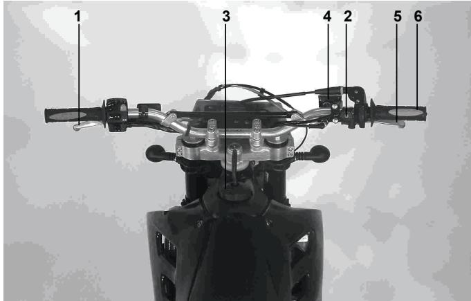
PETROL
The GAS GAS FSE / SM FSE 450 has a four stroke engine and requires 98 octane, unleaded petrol.
| Fuel Tank Capacity |
| 7.2L |
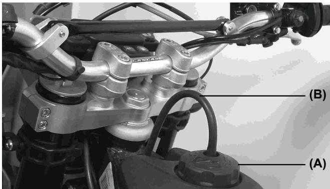
(A). Fuel cap.
(B). Fuel vent hose.
To open the fuel cap (A), release the fuel vent hose (B) from the handle bar and rotate the fuel cap in an anti-clockwise direction.
To close the fuel cap, rotate it in a clockwise direction.
RECOMMENDED FUEL
Use lead-free petrol with an octane rating equal to or higher than that shown in the table.
| OCTANE RATING METHOD | OCTANE RATING (MIN) |
| Antiknock Index (RON+MON)/2 | 90 |
| Research Octane No. (RON) | 98 |
NOTE
If knocking occurs, try a different brand of gasoline or higher octane grade.
WARNING
Gasoline is extremely flammable and can be explosive under certain conditions. Always stop the engine and do not smoke. Make sure the area is well ventilated and free from any source of flame or sparks; this includes any appliance with a pilot light.
SERIAL NUMBER
Printed on the steering tube. Indicates the frame number with which the motorcycle is registered.
Qualification approval plate
The motorcycle is fitted with its own corresponding qualification approval plate with the serial number, also printed on the steering tube and whose data also coincides with that in the documents.


STARTING THE ENGINE
- Ensure that the motorcycle is in neutral.
- Rotate the starter key clockwise (ON (A) position), in this way the electric circuits are active and the engine can start.
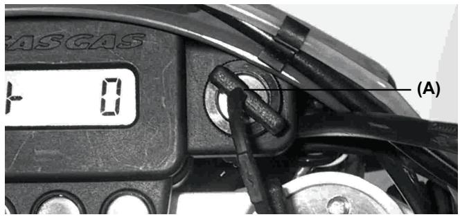
- Without using the throttle, press the electric start button (B).
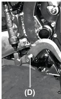
Stopping the engine
- Change gear to neutral.
- After a slight acceleration, release the throttle completely and rotate the ignition key anti-clockwise.

- The key should point left (D), this means that all of the electric circuits are inactive. The engine cannot start.
- The key may be extracted from the ignition.
NOTE
Starting the engine while the key is being turned to the ON position may cause a loss in battery power.
COLD STARTING
The cold start function is responsible for aiding the engine start if this is cold.
- There is no need to use the throttle, simply start the engine. Note that the engine will start after a certain number of revolutions.
After some seconds, the engine will be at normal operation temperature. The engine will reach its optimal temperature, in low time and without causing damage.
NOTE
- If the engine is flooded then start with the throttle fully open.
- The motorcycle may be started in gear if the clutch is disengaged.
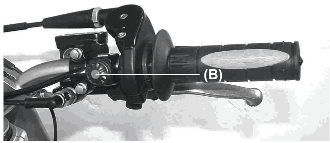
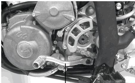
SHIFTINGGEARS
The transmission is a 6 speed, return shift type meaning that to go back to first gear from a higher gear, you must shift back through the gears one by one.
To engage first gear from neutral, pull in the clutch lever and push down on the shift pedal then release the pressure on the shift pedal and gently release the clutch lever.
CAUTION
When changing gears, press firmly on the shift pedal to ensure complete, positive shifting. Careless, incomplete shifts can cause the transmission to jump out of gear and lead to engine damage.

(B). Shift pedal.
STOPPING THE MOTORCYCLE
For maximum deceleration, close the throttle (A) and apply both front and rear brakes. Disengage the clutch as the motorcycle comes to a stop. Independent use of the front or rear brake may be advantageous under certain conditions.
Downshift progressively as speed is reduced to ensure good engine response when you want to accelerate.
BREAK-IN
To obtain the proper operating clearances in the engine and transmission that are necessary for smooth engine performance and reliability, an initial break-in must be completed. For the first hour or 100Km of operation, run the engine at low rpm.
NOTE
The slow speed necessary during the break-in period may cause carbon to build up on the spark plug and soil it. If inspection of the spark plug shows this to be the case, replace the standard spark plug with a higher heat grade spark plug for the duration of the break-in period.
Break-in following these steps:
- Start the engine and let it run at idle until the engine is thoroughly warmed up.
- Stop and let the engine cool completely
- Start the engine and ride for 10 minutes at moderate speed. NEVER ACCELERATE FULLY.
- Stop and let the engine cool completely. Check and adjust chain slack and spoke tightness and make a general inspection.
- Start the engine and ride for 20 minutes at moderate engine speed. NEVER ACCELERATE FULLY.
- Stop and let the engine cool completely. Check and adjust (4).
- Fit the inspected parts.
- Fill the radiator up completely with cooling liquid. Before starting the engine bleed the air from the cooling system.
- Start the engine and ride for 30 minutes at moderate speed.
- Stop and let the engine cool completely. Check and adjust (4).
- After the break-in procedure has been properly carried out, the motorcycle is ready for regular operation.
CAUTION
In any case, even an imprudent acceleration can cause engine trouble, take special care and use the proper skills and techniques required for correct driving of the motorcycle.
NOTE
Following the break-in, fit a new standard spark plug.
| MAINTENANCE CHART | |||
| Article | PeriodFirst 5 hours | PeriodEvery 30 hours | PeriodEvery 60 hours |
| Air filter | Inspect each time that the motorcycle has run or when necessary | ||
| *Exhaust connectors and bolts | T | T | T |
| *Valve tolerances | I | - | I |
| Spark plug | - | I | R |
| Injection pump pipes | I | I | I |
| *Revise every 4 years | |||
| Engine oil and filter oil | R | R | R |
| *Engine oil pipes | I | I | I |
| Coolant | - | I | I |
| Revise every 2 years | |||
| Radiator hoses | I | I | I |
| Clutch | I | I | I |
| Chain | Clean, lubricate and inspect each time the motorcycle has run | ||
| *Brakes | I | I | I |
| Brake lines | I | I | I |
| *Revise every 4 years | |||
| Brake liquid | I | I | I |
| *Revise every 2 years | |||
| Tyres | Inspect tyres for damage and check the tyre pressure every time the motorcycle has run | ||
| *Steering assembly | I | - | I |
| *Front forks | I | - | I |
| *Rear suspension | I | - | I |
| *Chassis bolts and nuts | T | T | T |
NOTE: I = Inspect and clean, adjust, replace or lubricate if necessary; R = Replace, T = Tighten, C = Clean
BATTERY
This battery is maintenance free and checking the fluid level is not required. It is advisable to check the charge of the battery periodically
To remove the battery, follow these steps:

- Remove the screws (A) and remove the seat (B).
-
Release the rubber (C).
-
Disconnect the terminals ensuring that they do not enter into contact with metal parts then extract the battery.
WARNING
Hydrogen gas produced by the battery may explode if exposed to open flame or sparks.
Keep the area ventilated and free from naked flames.
The operating instructions for the battery are as follows:
- Check the battery tension in open circuit status (disconnected).
- In case the battery's tension is below 12.60V , or if the storage period has exceeded 6 months, the battery has to be recharged following the instructions in paragraph 3.
If the battery voltage is above 12.60V , the battery can be installed on the vehicle without having to recharge it.
3.1. Constant voltage charge mode.
- Constant voltage = 14.40 - 14.70V
- Initial charge current = 0.1 - 0.5 Cn
- Charge duration = 6 hours minimum / 24 hours maximum.
3.2. Constant power charge mode.
-
Maximum charge current = 0.1Cn
-
Recommended charging duration = 5 - 8 hours.
- The product (charge current) X (charge duration) must be within the range: 0.5 - 0.8 Cn.
Note
In case that a different mode of charging is used to those established here, never exceed the maximum allowed currents nor the maximum charge duration of 24 hours.
| CAUTION |
| Not using the standard manner of charging may seriously shorten the battery life. Never exceed the standard charge. |
| CAUTION |
| Inverting the polarity of the battery terminals may cause battery charge problems and cause damage to the battery system. The red terminal is positive (+) and the black terminal is negative (-). |
THE COOLING SYSTEM
Radiator hose
Check the radiator hoses for cracks or deterioration, and connections for leaks.
Radiator
Check the radiator fins for obstruction by insects or mud. Clean off any obstructions with a stream of low-pressure water.
CAUTION
Using a high pressure water source could damage the radiator fins and render it ineffective.
Do not obstruct or deviate the radiator air intake by installing non-approved accessories. Interfering with the radiator could cause overheating and result in engine damage.
Coolant
This absorbs excessive heat from the engine and transfers it to the air at the radiator. If the coolant level becomes low, the engine overheats and may suffer severe damage. Check the coolant level each day before riding the motorcycle. Replenish coolant if the level is low.
WARNING
To avoid burns, do not remove the radiator cap or try to change the coolant when the engine is still hot. Wait for it to cool down.
Anti-freeze liquid information
To protect the cooling system aluminium parts (engine and radiator) from rust and corrosion, the use of corrosion and rust inhibitor chemicals in the coolant is essential. If coolant containing corrosion and rust inhibitor chemicals is not used, over a period of time, the radiator will rust. This will block the cooling hoses.
CAUTION
Use of incorrect coolant solutions will cause severe engine and cooling system damage.
Use coolant containing corrosion inhibitors made specifically for aluminium engines and radiators in accordance with the instructions of the manufacturer.
WARNING
Coolant chemicals are harmful to the human body. Follow coolant manufacturer warnings and coolant handing instructions.
CAUTION
Soft or distilled water must be used with the inhibitor chemicals and the antifreeze in the cooling system.
If normal water is used in the system, it the cooling system tubes may become blocked.
If the lowest ambient temperature encountered falls below the freezing point of water, protect the cooling system against freezing. Use a permanent type of anti-freeze (soft water and ethylene glycol plus corrosion and rust inhibitor chemicals for aluminium engines and radiators) in the cooling system.
For the coolant mixture ratio under extreme conditions, choose the mixture ratio listed on the container for the lowest ambient temperature.
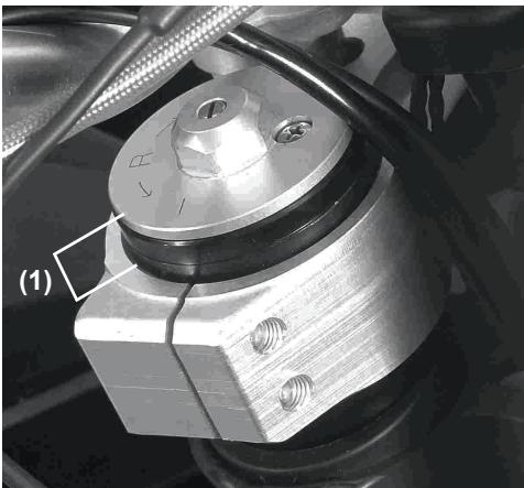
Coolant Level
- Situate the motorcycle so that it is perpendicular to the ground.
- Remove the radiator cap in two stages. First turn the cap anti-clock wise and wait for a few seconds. Then push and turn it further in the same direction to remove the cap.

(A). Radiator Cap.
CAUTION
Permanent types of antifreeze on the market have anticorrosion and anti-rust properties. When diluted excessively these lose their antifreeze and anticorrosion properties. These must be diluted in accordance with the instructions of manufacturer.
NOTE
Check the level when the engine is cold.
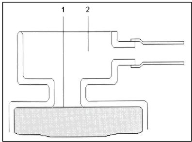
(1). Coolant level.
(2). Filler opening.
If the coolant level is low, add the correct amount of coolant through the filler opening.
Recommended liquid
Permanent type of antifreeze (distilled water and ethylene glycol) with corrosion and rust inhibitor chemicals for aluminium engines and radiators).
NOTE
Initially a permanent type of antifreeze is installed in the cooling system by the manufacturer. This is green in colour, containing 50% ethylene glycol with a freezing point of -35^ .
Total quantity
Mix antifreeze and distilled water 1:1 (distilled water 50% , antifreeze 50% ).
Changing the coolant
- The coolant should be changed periodically to ensure long engine life.
- Wait for the engine to cool completely.
- Situate the motorcycle so that it is perpendicular to the ground.
- Remove the radiator cap.
- Place a container under the coolant drain plug, and drain the coolant from the radiator and engine by removing the drain plug at the bottom of the water pump cover. Immediately wipe or wash off any coolant that spills on the frame, engine, or wheels.
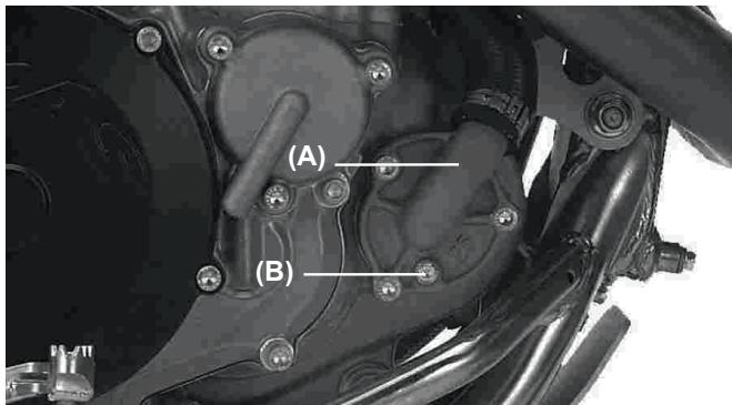
(A). Water pump cover.
(B). Coolant drain Plug.
| WARNING |
| If coolant gets on the tyres this will make them slippery and could result in an accident. |
-Inspection of the coolant. If white cotton-like patches appear in the liquid then this means that the aluminium elements of the cooling system are corroded. If the liquid is brown then this means that the steal or iron parts of the system are oxidized. In either case clean out the system.
- Check the cooling system for damage, loose joints, or leaks.
- Install the water pump cover drain plug and cylinder drain plug with the specified torque shown in the table. Always replace seals with new ones.
Bolt torques: Water pump plug: 9 Nm.
- Fill the radiator up to the edge and install the radiator cap.
- Check the cooling system for leaks.
- Start the engine, warm up the engine, and then stop it.
- Check the coolant level after the engine cools down. Add coolant up to the bottom of the radiator filler neck.
SPARK PLUG
The standard spark plug is shown in the table and is tightened to 11 Nm.
Standard spark plug
NGK CR8 E or DENSO U24ESR-N 0.7-0.8 mm.
The spark plug should be taken out periodically to check the electrode gap. If the plug is oily or has carbon build up on it the clean it with a sand blaster. Following abrasive particle cleaning, the spark plug should be cleaned with a wire brush or similar. Measure the distance
between electrodes using a gauge and adjust in case that it is not correct by bending the outer electrode. If the spark plug electrodes are oxidised, damaged or the insulation is broken then replace the plug.
NOTE
Inspect every 30 hours. Replace every 60 hours.
To find the correct heat grade spark plug is being used, take it out and examine the insulation around the electrode. If the ceramic is light brown, the spark plug is correctly matched to engine temperature. If the ceramic is white, the plug should be replaced with the next coldest plug. If the ceramic is black, the plug should be replaced with the next hottest plug.
NOTE
If the engine output decreases, replace the spark plug to regain performance.
Spark plug maintenance
| NGK | DENSO | COMMENTS |
| CR7E | U22ESR-N | If the standard spark plug is wet then replace it. |
| CR8E | U24ESR-N | Standard |
| CR9E | U27ESR-N | If the standard spark plug looks glassy or has a white colour, replace it |
CUIDADO
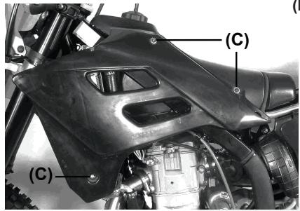
- Remove the bolts (C) (left and right).
- Remove the rubber attachment on the tank (D).
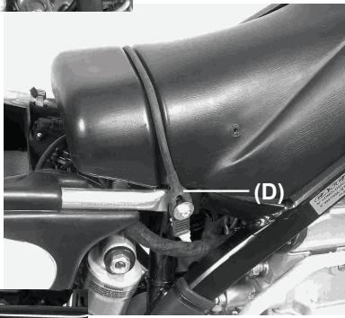
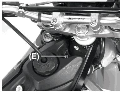
-
Remove the tank securing bolt (E).
-
Separate the connectors from the electronics (F).
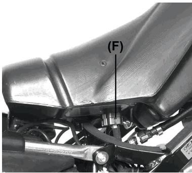
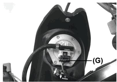
- Separate the connector (G) from the fuel pump and secure to one side of the tank.
WARNING
When the injection pump pipes are removed, petrol may be spilled and cause a fire.
- Stop the engine before removing the tank. Keep naked flames and sparks away from the tank cap. Do not smoke.
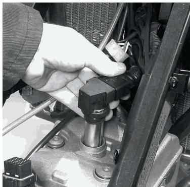
- Remove the spark plug hood.
NOTE
A cap protects the spark plug.
Keep this clean and dry.
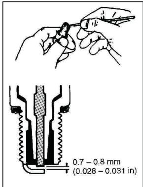
- Take out the spark plug and clean carbon deposits from the spark plug with a small tip or a metallic brush. Readjust the gap in the plug between 0.7 and 0.8mm (0.028 - 0.031 in).
Before removing the carbon deposits, check its colour; this colour tells us whether the standard plug is the best for our use.
AIR FILTER
An obstructed air filter restricts the air intake of the engine, increasing the petrol consumption and reducing the engine power as well as the destruction of the spark plug.
WARNING
An obstructed air filter may allow dirt to enter into the injector blocking it open; this could lead to an accident.
CAUTION
An obstructed air filter will allow dirt to enter the engine causing excess wear and engine damage.
Inspect this without fault, before and after each race or session. Clean if necessary.
Cleaning the air filter
WARNING
Clean the filter in a well-ventilated zone and ensure that there are no sources of naked flame or sparks near the work area (including the focus of a powerful light). Do not use petrol to clean the filter as this could result in an explosion.
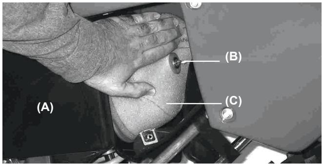
-Remove the cap (A).
-Remove the screw (B) and take the filter out (C).
Stuff a clean, lint-free towel into the intake manifold so that no dirt is allowed to enter.
CAUTION
Do not spin the filter on its cage. It is possible to tear or damage the filter.
- Clean inside the filter housing using a damp cloth.
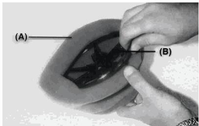
Remove the cage (B) from the air filter (A).
- Clean the filter in a filter bath using a soft brush.

-
Squeeze it and take it out with a clean cloth.
-
Check the air filter for damage such as scraping, hardening, shrinkage. If it is damaged then replace otherwise dirt will enter the throttle body.
- Grease all of the connections and bolts of the air filter and inlets.
Install the filter in the cage and cover the filter lip (A) with a thick layer of grease to ensure a seal and to avoid dust penetration.
- Fit the air filter to the motorcycle and ensure that it is correctly connected.
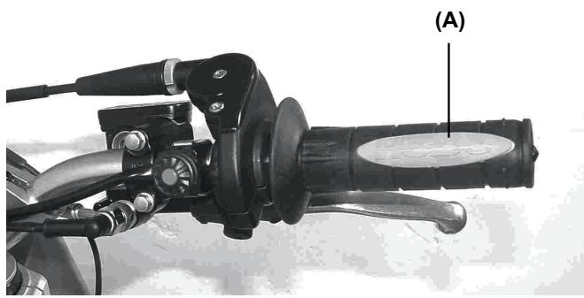
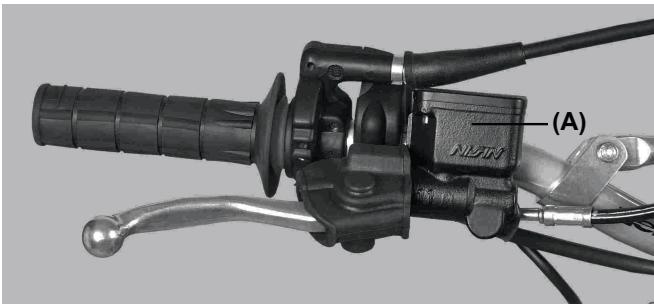
THROTTLE CABLE
- Check that the throttle grip turns smoothly
- Check that the throttle grip has 2 - 3mm of play.
- If the play is incorrect, loosen the locknut on the upper end of the throttle cable, and turn the adjuster to obtain the correct amount of play.
- Tighten the locknut.
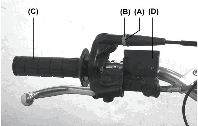
(A). Adjustment.
(B). Lock nut.
(C). Throttle grip.
(D). Brake fluid reservoir.
- If the play can not be established by adjusting the cable, remove the cable protection from the throttle, adjust this using a tensioning device at the end of the cable, tighten the lock nut and refit the protection.
CLUTCH
Proper clutch lever play is 2-3 mm. Play increases with the clutch wear and thus requires adjustment.
When there is too much play, first try to adjust the level of the clutch lever.
Tighten the adjustment bolt to obtain the optimal play.
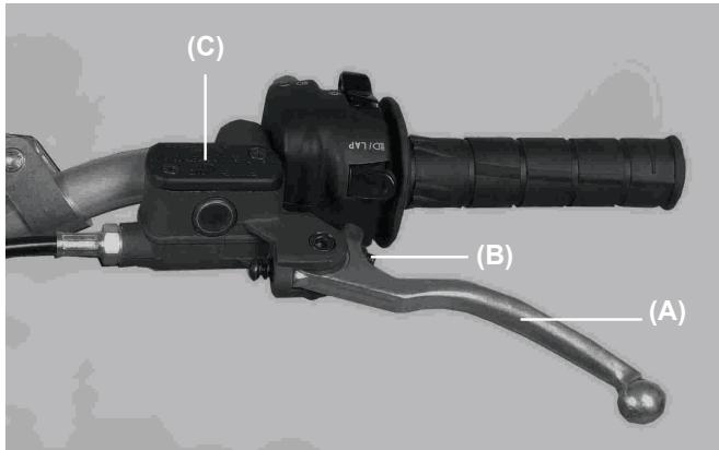
(A). Clutch Lever.
(B). Clutch cylinder piston rod.
(C). Hydraulic fluid tank.
If the adjustment of the clutch lever has reached its limit, then play must be adjusted by the clutch cylinder piston rod.
THE EXHAUST SYSTEM
The exhaust and the silencer reduce noise and carry the gasses away from the driver.
If the exhaust is damaged, rusted, dented or split then change it. Change the silencer packing if the noise begins to be too loud or if the engine performance drops.
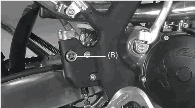
Changing the silencer
- Remove the right side number carrier cover.
- Release the exhaust flange.
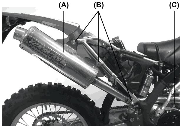
(A). Silencer.
(B). Silencer attachment bolts.
(C). Flange.
Changing the silencer packing
- Remove the cover rivets (A).
- Extract the silencer cover (B).
- Pull out the inner silencer.
- Change the silencer packing by wrapping around the inner tube.
- Refit the assembly.
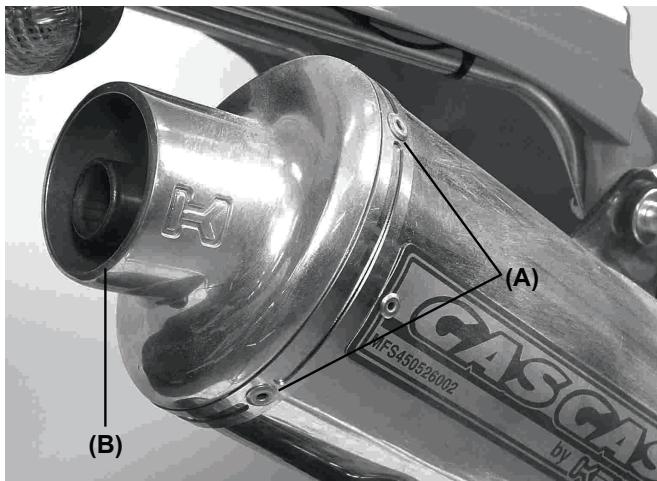
(A). Rivets.
(B). Cover.
CHAINGUIDE
The drive chain must be checked, adjusted, and lubricated in accordance with the Periodic Maintenance table in order to prevent excessive wear. If the chain is worn or badly adjusted (to tight or loose) then it may jump off the sprockets or break.
WARNING
A chain that breaks or jumps off the sprockets could snag on the engine sprocket or lock the rear wheel, severely damaging the motorcycle and causing it to go out of control.
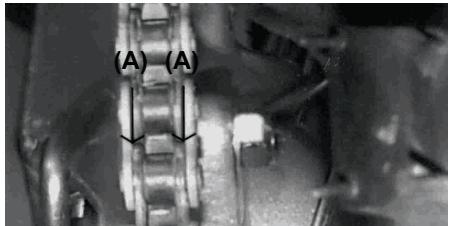
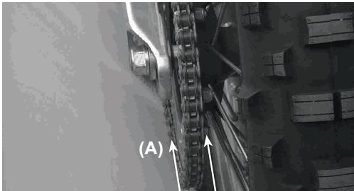
Checking tension
The space between the chain and the swing arm at the rear of the chain slider should be 30 - 50mm . Rotate the rear wheel to find the place where the chain is tightest. Adjust the drive chain if it has too much or too little slack.
NOTE
In muddy or humid conditions, the mud gets inside the chain increasing tension and may cause the chain to break. To prevent this, adjust the chain to 30 - 50mm of space between the chain and rocker arm whenever necessary.
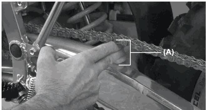
(A). 30 - 50mm
In addition to checking the slack, rotate the rear wheel to inspect the drive chain and sprockets for damaged rollers, loose pins and links, unevenly or excessively worn and damaged teeth.
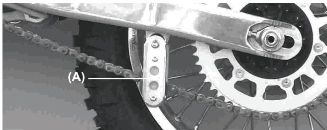
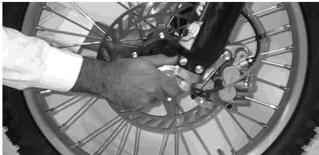
Tension adjustment
-Loosen the rear axle nut.
- Turn the nuts on the chain adjusting bolts evenly until there is 30-50 mm of space between the chain and the swing arm. To keep the chain and wheel aligned, the adjustment on the left of the chain should be equal to that on the right.
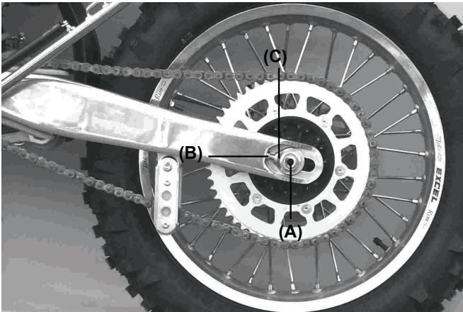
(A). Rear axle.
(B). Adjustment nut.
(C). Chain adjustment.
NOTE
Wheel alignment can also be checked using the straightedge or string method.
WARNING
Misalignment of the wheel will result in abnormal wear and may result in an unsafe riding condition.
- Tighten the chain adjustment nuts.
- Tighten the axle nut to 98 N-m.
- Rotate the wheel, measure the chain slack again at the tightest position, and readjust if necessary.
WARNING
If the axle nut is not securely tightened unsafe riding conditions may result.
Drive chain, chain guide, chain slide, and rear sprocket
When the chain has worn so much that it is more than 2% longer than when new, it is no longer safe for use and should be replaced. Whenever the chain is replaced, inspect both the engine pinion and rear sprocket, and replace them if necessary. Worn teeth will cause the chain to wear more quickly.
NOTE
For maximum resistance and safety, a genuine part must be used for replacement.
To minimize any chance of the master link coming apart, the master link clip must be installed with the closed end of the «U» points in the direction of chain rotation.
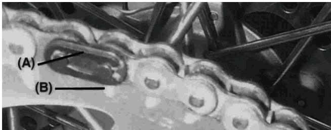
(A).Clip.
(B). Chain direction of rotation.
Chain Wear Guide
Visually inspect the drive chain wear guide (A); If the guide is worn excessively or damaged, replace it.
Chain guide slide
Visually inspect the upper and lower part of the chain slider on the swing arm. If this is worn then replace it.
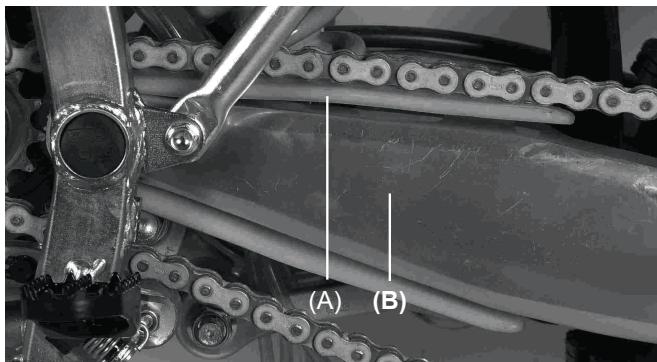
(A). Chain guide slide.
(B). Rocker arm.
Pinion and sprocket teeth wear
Visually inspect the pinion and sprocket teeth.
If they are worn or damaged, replace the pinion or sprocket.
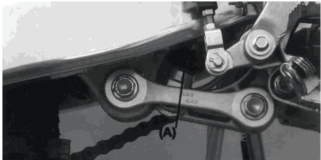
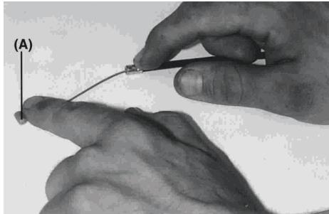
Lubrication
Lubrication is necessary after riding through rain or in the mud, or any time that the chain appears dry. A heavy oil is preferred to a lighter oil because it will stay on the chain longer and provide better lubrication.
Apply oil to the side of the links so that it will penetrate better. Wipe off any excess oil.
(A). Apply oil.
HANDLEBARS
To suit various riding positions, the handlebar position can be adjusted front to rear.
Handlebar position adjustment
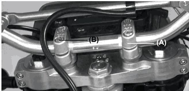
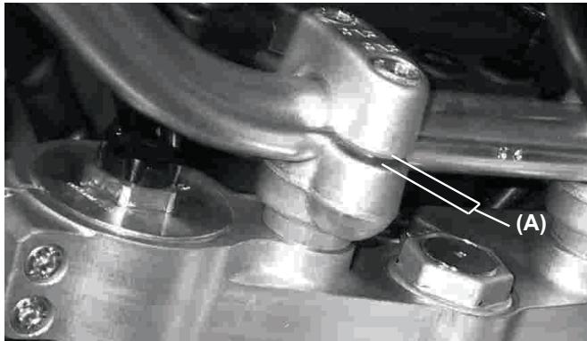
Loosen the handlebar holder bolts (B), of the handlebar holder (A) then rotate bars to desired position.
Tighten the bolts securely; first the forward bolts then the rear, to a torque of 25Nm . If the handlebar is correctly installed, there will be a minimal gap at the front and rear of the clamp after tightening (A).
BRAKES
Disc and disc pad wear is automatically compensated for and has no effect on the brake lever or pedal action. So there are no parts that require adjustment on the brakes except brake lever play and the brake pedal position and play.
Front brake lever
Adjust brake lever to a comfortable position. To adjust, loosen the nut under the rubber protection (B). Tighten after adjustment. Ensure that the brake responds correctly.
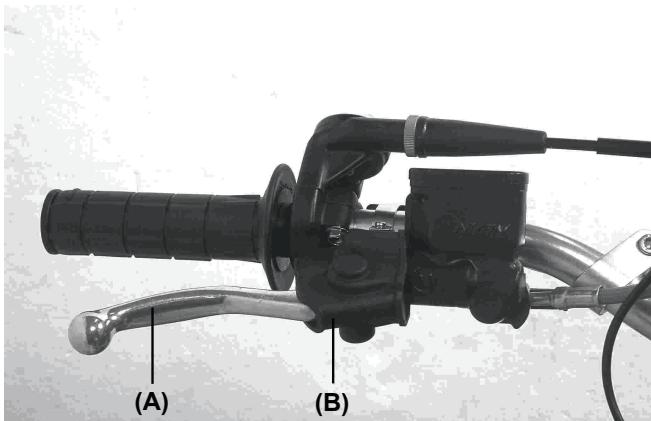
(A). Brake lever.
(B). Rubber protection.
Rear brake pedal
When the brake pedal is in rest position, there should be a play of 10mm . If not, then adjust this.
Ensure that the brake responds correctly and does not rub. To adjust the pedal play, loosen the locknut, rotate the bolt and retighten the locknut.
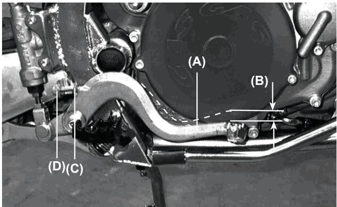
(A). Brake pedal.
(B). 10mm of play.
(C). Adjustment bolt.
(D). Lock nut.
WARNING
If the brake lever or pedal feels mushy when it is applied, there might be air in the brake lines or the brake may be defective. Since it is dangerous to operate the motorcycle under such conditions, check the brakes immediately.
Brake fluid
Regularly check the brake fluid and periodically change it. It should also be changed if it is contaminated by water or dirt.
Recommended liquid
Use D.O.T 3 or D.O.T 4
Fluid level inspection
The front (A) and rear (B) reservoirs must be kept more than half full with brake fluid. If the amount of brake fluid is insufficient, add brake fluid.
CAUTION
Do not spill brake fluid onto any painted surface. Do not use fluid from a container that has been left open or that has been unsealed for a long time. Check for fluid leakage around the fittings. Check for brake line damage.
WARNING
Do not mix brands of fluid. Change the brake fluid in the brake line completely if the brake fluid must be refilled with a type other than the brake fluid already in the reservoirs.
Brake Wear Inspection
If the thickness of either pad is less than 1mm , replace both pads in the calliper as a set. Pad replacement should be done by an authorized GAS GAS dealer.
STEERING
The steering should always be kept adjusted so that the handlebar will turn freely but without excessive play.
To check the steering adjustment, lift the bike off the ground using a stand underneath the chassis. Push the handlebar lightly to either side; if it continues moving under its own momentum, the steering is not too tight. Squatting in front of the motorcycle, grasp the lower ends of the front fork at the axle, and push and pull the bottom end of the front fork back and forth; if play is felt, the steering is too loose.
If the steering needs adjustment
- Using the stand under the frame, stabilize the motorcycle.
- Place a stand or block under the engine to raise the front wheel off the ground.
- Remove the handlebar by loosening the handlebar clamp bolts (A).
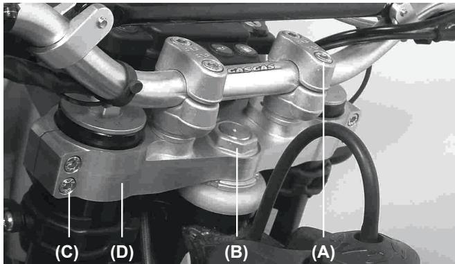
- Loosen the steering stem bolt (B).
- Loosen the bolts for the upper suspension plate and remove it (C).
-
Rotate the steering adjustment bolt using the special spanner in order to obtain the appropriate adjustment.
-
Install the upper suspension plate (D).
- Tighten the steering stem nut (B), the washers and bolts on the front forks to the correct torque.
Steering head nut: 44 Nm (4.5 Kgm)
Suspension plate bolts: 22 Nm (2.25 Kgm)
- Recheck the steering and readjust if necessary.
- Refit all removed parts.
STEERING LOCK
This mechanism allows us to lock the steering. It is located on the steering tube.
The handlebars must be turned to the right completely, then insert the key, rotate left, press, rotate right and take the key out.
(A). Steering lock.
CAUTION
Never leave the key in the lock. If the steering is turned to the left with the key in the lock then this will be severely damaged.
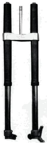
FRONT FORKS
The front fork should always be adjusted for the rider's weight and track conditions. The adjustments are done in 5 stages: - Air pressure: affects the entire range of fork stroke. The air pressure increases when the forks heat up, or, as operation time increases. We don't recommend using air pressure as the forks are designed to work without adding any air.
-
Rebound and compression dampening adjustment: This adjustment affects the speed of the rebound. The fork rebound dampening adjustment has 18 positions. The tightened position is completely hard. The position 12 from the closed position is the standard and the position 18 is totally soft.
-
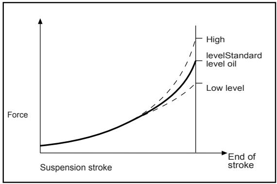
Oil level adjustment: The effects of higher or lower fork oil level are only felt during the final 100mm of fork stroke. A higher oil level will make the fork rebound more quickly. A lower oil level will make the fork rebound more slowly.
-
Fork springs: Optional springs are available that are softer and stiffer than standard.
Air Pressure
The standard air pressure for the front forks is atmospheric pressure. The air pressure in the fork legs increases as operation progresses and therefore the forks become harder.
- Using a stand underneath the chassis, stabilized the bike.
- Put something under the engine so that the front wheel does not touch the ground.
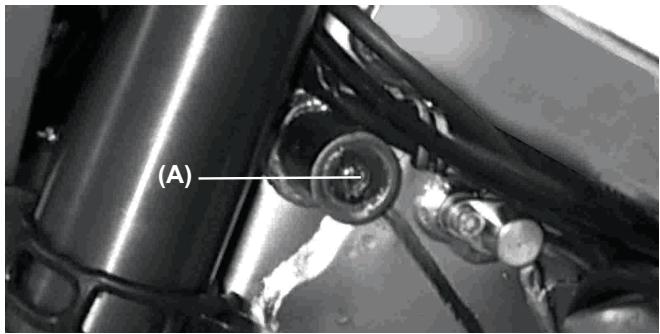
- Remove the air purge screw from the upper part of the front forks.
(A). Purge bolt.
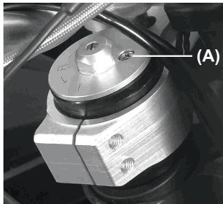
Adjusting the extension
- To adjust the rebound, rotate the adjustment control (A) on the upper part of the front forks using a screwdriver.
- Adjust the rebound according to your preferences under determined conditions.
(B). Adjustment control.
Adjust the return to the standard measures (rotating anti-clockwise, 6 positions).
CAUTION
The front fork left and right tubes must be at the same level and aligned with the plate.
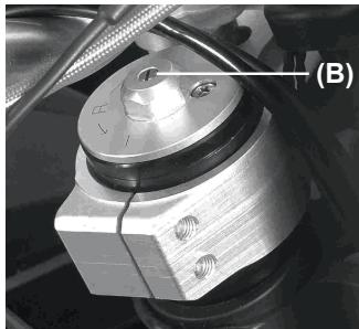
Adjusting the compression
- To adjust the compression, rotate the adjustment control on the upper part of the front forks by hand.
- Adjust the compression suited to your needs under certain conditions. Adjust the compression to the standard measures (rotating anticlockwise, 6 positions).
Adjusting the oil level
- Using the stand under the frame, stabilize the motorcycle upright.
- Take out the handlebar bolts and take out the handlebars.
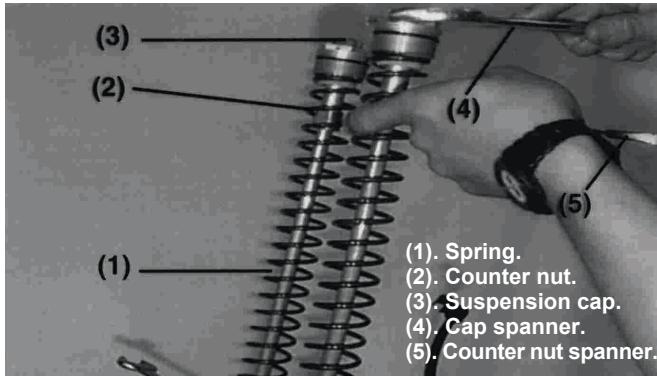
- Remove the suspension caps from the rods.
- Slowly compress the front forks all the way.
- Lift the fork springs.
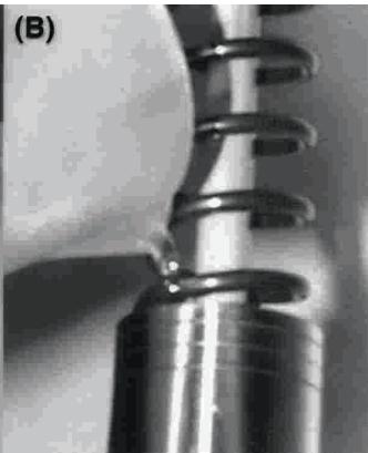
- Holding the suspension rod cap with a spanner, loosen the cap locking counter nut.
- Remove the suspension rod caps.
- Remove the suspension spring guide.
- Using a spanner, remove the springs from the forks.
- Place the oil level indicator on the upper part of the fork tube and measure the distance from the upper part to the oil level.
Standard oil level
Marzocchi: 110 mm
WP: 120 mm
(A). Releasing oil.
(B). Filling oil.
Adjust to the level of oil required in the tables using the following oil:
Recommended oil
MARZOCCHI: SAE 7'5
WP:SAE 5
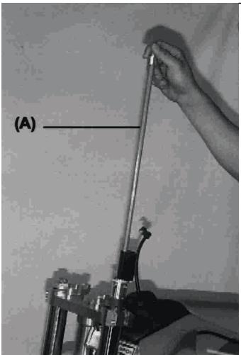
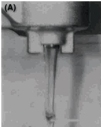
(A). Hydraulic rod
- Pull on the hydraulic rod (A) slowly.
- At this time, the fork oil comes out of the push rod hole, let it overflow until it stops.
- Put the fork spring (1) into the fork tube.
- Tighten the suspension spring and insert the spanner (5) onto the cap lock (3) counter nut (2).
- Fit the suspension cap (3) to the fork tube and tighten to 29Nm .
- Fit the other fork.
- Refit all removed parts.
Suspension rod spring
Different springs can be used depending on the weight of the driver and the track conditions.
- Hard springs make the forks harder and the rebound faster.
- Light springs make the forks softer and the rebound slower.
Suspension plate position
Ensure that the tyre does not touch the mudguard when the forks are fully compressed. There should be at least 5 mm clearance.
| CAUTION |
| The right and left suspension rods must be adjusted equally. |
(1). Fork tube height
REAR SUSPENSION
The rear suspension is made up of a shock absorber, swing arm, tie rods and rocker arm.
In general the operating characteristics of the single shock are similar to the front fork however this is characterized as well as by the shock, the articulated quadrangle composed of the rods and rocker arm.
To suit various riding conditions, the spring preload of the shock absorber can be adjusted or the spring can be replaced with an optional one. Also the dampening force can be adjusted easily so changing oil viscosity is unnecessary.
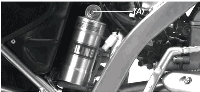
Extension adjustment
To adjust this, rotate the control on the rear of the shock by hand until noting a click.
There is a possibility of 60 "Clicks" in total.
The standard rebound is at : 25 “Clicks”.
(Anti-clockwise from the completely closed position).
(A). Rebound adjustment
Compression adjustment
To adjust, rotate the control on the gas reservoir using the point of a screwdriver until noticing a «click».
There is a possibility of 60 "Clicks" in total.
The standard rebound is at: 30 "Clicks".
(Anti-clockwise from the completely closed position).
(A). Compression adjustment.
Spring adjustment
- Remove the seat and the side covers.
- Loosen the bolt of the air filter conduit clamp.
- Remove the silencer.
- Remove the sub chassis with the air filter housing.
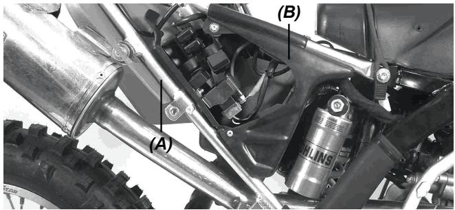
(A). Sub chassis.
(B). Filter housing.
Suspension spring
The standard spring is a 4.0. The length of the preloaded spring with the shock in rest position is 258~mm .
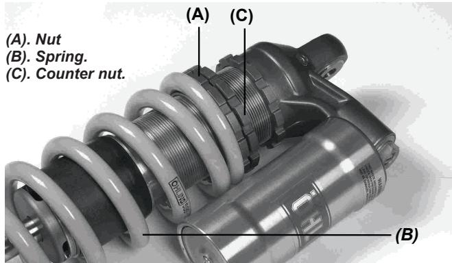
- Tighten the counter nut correctly.
- Following the adjustment, move the spring up and down to ensure that this is correctly in place.
- Refit all removed parts.
Rear shock absorber spring replacement
Stiffer or softer springs are available. If the standard spring is unsuitable for your purpose, select a proper one according to the rider's weight and course conditions.
- Use of a stiffer spring: faster rebound.
- Use of a softer spring: slower rebound.
NOTE
See the adjustments page 47.
WARNING
Improper removal of the spring from the rear shock absorber body may cause the spring and associated parts to be ejected at high velocity. Always wear eye and face protection. Removal and installation of spring should be performed by an official distributor.
WHEELS
Tyre
. Tyre pressure affects traction, handling, and tyre life.
. Adjust the tire pressure to suit track conditions and rider preference, but do not deviate excessively from the recommended pressure.
NOTE
Tyre pressure should be tested when the tyre is cold before driving.
Track conditions
- When the track is wet, muddy, sandy or slippery, reduce the tyre pressure.
- When the track is stony or hard, increase the tyre pressure.
Spokes and rims
The spokes on both wheels must all be tightened securely and evenly and not be allowed to loosen, Unevenly tightened or loose spokes will cause the rim to warp, hasten nipple and overall spoke fatigue, and may result in spoke breakage.
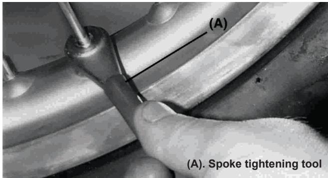
Centring the rim
Put a quadrant gauge next to the rim and rotate the wheel to measure the axial centring.
Put the dial on the inside of the rim circumference, rotate the wheel and the difference between the largest and smallest measurement is the centring measurement.
If the wheel is slightly off-centre then this can be corrected by loosening certain spokes and tightening others in order to change the rim position. If the rim is bent or crooked then it must be replaced.
NOTE
A soldered area on the rim may give an excessive reading. Ignore this while measuring the centring.
Cleaning
1- Preparation for cleaning
Before cleaning the motorcycle must be prepared so that water does not penetrate certain areas of the bike.
The exhaust: Once this is cold, cover it with a plastic bag attached with rubber.
Clutch and brake levers, grips and stop button: cover with a plastic bag.
Air filter intake: cover this with insulation tape or a cloth.
2-Where to be careful
Avoid spraying water with any great force near the following places: Disc brake master cylinders and callipers; under the fuel tank (If water gets into the ignition coil or into the spark plug cap, the spark will jump through the water and be grounded out; the affected parts must be dried).
Front and rear hubs.
Steering pivots (steering tube).
Rear suspension system.
Swing arm pivots.
3- After cleaning
- Remove the plastic bags and clean the air filter intake.
- Lubricate the locations listed in the lubrication section.
- Start the engine and let it heat for 5 minutes.
- Check the brakes before driving the bike.
WARNING
Never wax or lubricate the brake disk, this could lead to brake failure and could provoke an accident. Clean the disk using trichloroethylene or acetone.
Tighten bolts and nuts
Every day before using the bike, rapidly ensure that all bolts and nuts are tightened. Also make certain that all of the other fastenings are in place and in good condition.
1-Front and rear wheels
2-Front forks
3- Handle bars
4- Clutch lever support bolt
6- Air filter housing bolts
7- Seat support bolts
8- Spokes
9- Disk plate screws
10- Front axle bolt
11- Brake attachment bolt
12- Sub chassis support bolt
13-Radiator support bolts
14- Nuts and bolts of the engine mounting
15-Shift pedal bolts
16-Chain guide bolts
17-Chain adjust bolt
18-Rear axle bolt
19-Silencer support bolts
20- Sub chassis bolts
21- Rear shock bolts
22- Exhaust flange bolt
23- Upper suspension plate bolts
24- Steering head nut
25- Brake lever support bolt
26- Rod support bolt
27- Rear brake pedal bolt
28- Rod support bolt Rocker
29-Rocker arm bolt
TIGHTENING TORQUE TABLE
Tighten all of the bolts and nuts using the correct spanners. If not correctly tightened then motorcycle damage or even an accident could occur.
| PART NAME | Nm | Kgm | |
| ENGINE | Engine drain plug | 20 | 2,0 |
| Kick pedal bolt | 20 | 2,0 | |
| Kick pedal nut | 25 | 2,5 | |
| Shift pedal bolt | 10 | 1,0 | |
| Spark plug | 11 | 1,0 | |
| Water pump cover drain plug | 9 | 0,9 | |
| CHASSES | Calliper mounting bolts | 25 | 2,5 |
| Disc plate mounting screws | 10 | 1,1 | |
| Engine mounting bolts | 36 | 3,6 | |
| Front axle bolt | 51 | 5,1 | |
| Front brake lever support bolt | 6 | 0,6 | |
| Fork flange bolt | 29 | 3,0 | |
| Steering nut | 98 | 10,0 | |
| Rear axle nut | 98 | 10,0 | |
| Rear brake pedal bolt | 9 | 0,9 | |
| Sub frame support bolt | 26 | 2,7 | |
| Rear shock absorber bolt | 39 | 4,0 | |
| Rear disc wheel drive bolt | 29 | 3,0 | |
| Spokes | 1.5 | 0,15 | |
| Steering axle bolt | 4 | 4,5 | |
| Rocker arm bolt | 81 | 8,3 | |
| Rod bolt | 81 | 8,3 |
LUBRICATION
Lubricate the points shown here, with either motor oil or regular grease, periodically or whenever the vehicle is wet, and especially after using a high-pressure spray washer. Before lubricating each part, clean off any rusty spots with rust remover and wipe off any grease, oil, dirt, or grime.
General lubrication
- Clutch lever (A).
- Front brake lever (B).
- Rear brake pedal (C).
Rear brake bearing (D).
-Shift pedal (E).

(E)
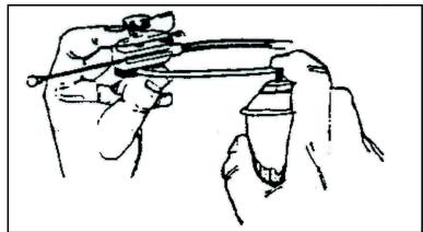
Use an aerosol with a pressure tube to lubricate
Use grease on the inner throttle cable
Chain lubrication
Lubricate the chain after wet terrain or when the chain looks dry. A high viscosity oil rather than low viscosity oil is better because it will stay a long time in chain providing lubrication.
Put oil on the sides of the chain rollers (A) so that it penetrates into these; remove excess oil.
(A).Greasing.
ENGINE OIL
Use a premium 4-stroke engine oil to lengthen the life of your motorcycle. Use oil classification SF or SG under the API classification.
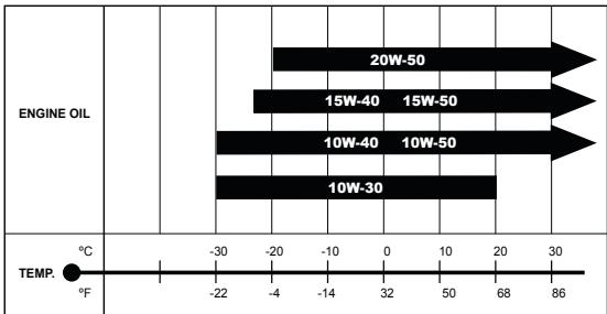
The recommended viscosity is SAE 10W-50; if an SAE 10W-50 oil is not possible use an alternative according to the table above.
Checking the oil level and making the changes periodically are two very important operations to keep the engine in perfect shape.
Initially replace the oil after 5 hours of operation and then every 60 hours.
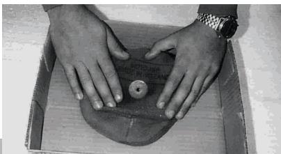
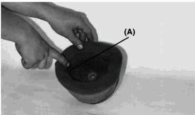
Checking the oil level
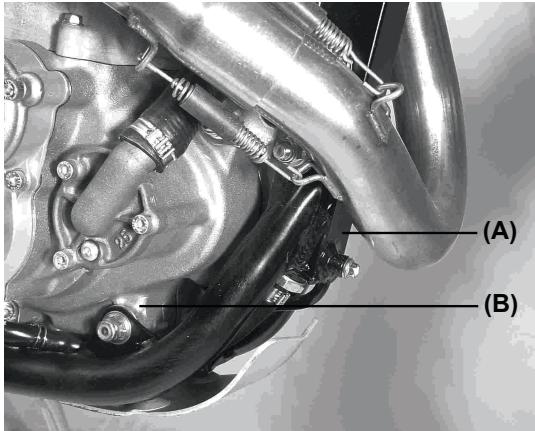
Fig. (A) The oil is located in the oil reservoir when the engine is running.
Fig. (B) If the bike has been stopped for a week, all the oil is in the engine crank case.
The oil is pumped from the oil reservoir to the engine when the engine is running. The engine oil reservoir is located in the top front part of the frame. The oil level drops when the bike is not in use. The oil drips down to the engine crankcase. To check the oil level, follow these instructions:
If the bike has been stopped for a week, we can be sure that all the oil is within the engine crank case.
- Start the engine and leave the motorcycle in neutral 3 minutes.
NOTE
When starting the engine, closely follow care and warnings from the section on starting the engine.
- Stop the engine and wait three minutes.

3. Take out the oil dipstick (A).
- Wipe the dipstick clean with a rag.
- Keeping the motorcycle upright vertically, put the dip stick back in all the way without screwing into place.
- Remove the dip stick and check the oil level. Oil level must be between line (L) (LOW) and (F) (FULL). If that is not the case, fill up the reservoir until the level reaches just the (F) line.
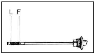
CAUTION
The level of the motor oil has to be between line (L) and line (F), engine damage may occur otherwise.
Check the oil level with the dipstick, with the bike in a completely upright position, every time you are going to use the motorcycle.
NOTE
The engine oil expands and thus the level increases when it is hot.
Check and adjust the level when the motor oil is not hot.
Changing the oil and filter
The oil should be changed when the engine is hot, since this helps the oil to go out through the drain located in the lowest part of the engine.
WARNING
The engine oil and the exhaust manifold can be very hot and cause burns.
Wait until the oil and the exhaust manifold are a little cooler.
WARNING
Engine oil is a health risk. Avoid any contact with this given that this could provoke irritations and, in the worst cases, skin cancer.
- Keep new or used oil away from the reach of children and animals.
- Clean clothes sleeves and pants.
- Wash yourself with soap if oil has been in contact with your skin.
To change the oil, follow the following steps:
- Place a recipient underneath the crankcase.
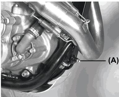
- Using a funnel drain the engine oil by removing the cap (A).
NOTE
Put used motor oil in an appropriate container for recycling.
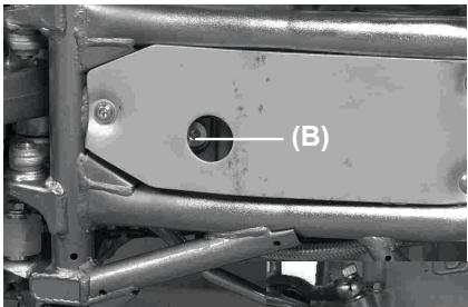
- Drain the engine oil by removing the cap (B), keep the motorcycle vertical.
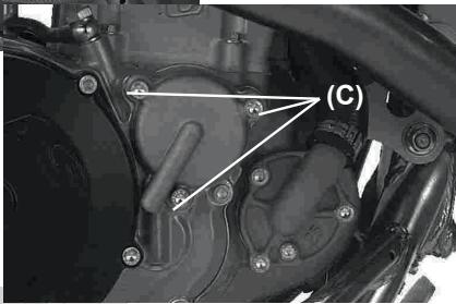
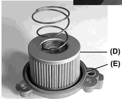
- Remove the three screws next to the filter cover (C).
- Remove the filter cover, pull on the filter element (D) to extract it and replace it by a new one.
WARNING
Using a filter with an incorrect design may cause engine malfunction. Use the oil filter with the genuine GAS GAS design or equivalent for your motorcycle.
WARNING
An error in the fitting of a new element may cause engine malfunction. The engine oil will not flow if a new element is not correctly fitted.
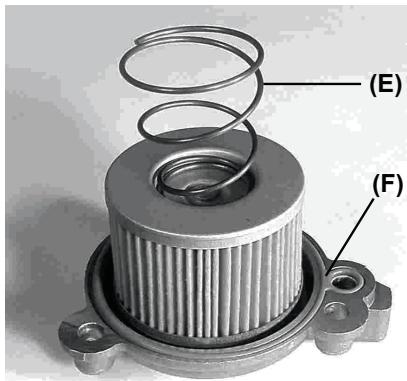
- Before replacing the oil filter, make sure that the spring (E) and the o-ring (F) are in the correct position.
NOTE
Fit a new O-ring when the filter is being replaced.
- Replace the filter cover and put the screws that secure the cover, but without tightening them too hard (do not exceed the recommended torque).
- Replace the drain caps and screw them back on accordingly. Pour new oil through the dipstick hole. Approximately 1200ml or else the required amount.
WARNING
The engine may be damaged if the oil is not used properly or the specifications recommended by GAS GAS MOTOS are not followed. Use the type of oil specified in the section on Petrol and Oil recommendations.
- Start the engine and allow it to run some minutes. Check for oil leaking from the filter cover.
- Check that the oil level is correct according to the oil level verification process.
TUNING THE SUSPENSION
No area of machine adjustment is more critical than proper suspension tuning; an incorrectly tuned suspension will keep even the best rider from attaining the full benefit of his machine's ability Check the suspension according to the pilot and the conditions of the terrain. When tuning the suspension don't forget:
- If the machine is new, break-in the suspension with at least one hour of riding before making any setting evaluations or changes.
- The major factors which must be considered in suspension tuning are: rider weight, rider skill and the track conditions (as well as the rider's style and positioning on the machine)
- If you have a problem, test by changing your riding posture or position so that the cause of the problem can be deduced.
- It is a wise practice to adjust suspension settings to suit the rider's strong points. If you are fast through the corners, adjust the suspension to allow fast cornering.
-Make setting changes in small increments; a little bit goes a long way, and it is very easy to over adjust a setting. - The front and rear suspension should be balanced; when one is changed, the other should be changed similarly.
When evaluating suspension performance the rider must make every effort to ride consciously and recognize the effects of his changes;
such things as changes in rider position and increasing fatigue may lead to incorrect judgments about required setting adjustments. - When the proper settings have been determined for a particular track, they should be written down for reference when returning to that track.
- Lubricate the bearings of the swinging arm, rods, rocker and joints before making changes and every 5 refills to prevent excess friction affecting the operation of the suspension.
Front forks
The fork oil level is adjustable. A change in the oil level will not affect the lower part of the stroke, but it will affect the upper part. - When the oil level is raised:
The spring effect becomes more progressive, and the front fork action feels 'harder' in the later stage of travel, near the bottom of the stroke.
- When the oil level is lowered:
The spring effect becomes less progressive, and the front fork action feels softer near the bottom of the stroke.
- Change the fork oil level correctly to make the forks work more at the end of fork travel.
- If fork bottoming is experienced, raise fork oil level in 10mm increments. This increase will cause a change in the upper stroke of the spring.
Adjusting the oil level
Adjust the oil level of the front forks (see the maintenance chart).
Changing incorrect adjustments
Listed below are some symptoms of improper suspension settings and the most adequate means of correcting them.
The proper settings can be achieved by applying the information in this chapter in a scientific manner. Simply take time a think about the changes you believe necessary, check them against the symptoms and cures described here, make the changes in small increments, and take notes on the changes and their effects.
Front fork symptoms
- The front forks are too stiff
Rebound adjustment incorrect.
The springs are too strong.
Too much oil.
Oil too dense.
-
The front forks stiffen at the end of the stroke
. The fork oil level is too high. -
The front forks operate but ride is too hard
Oil too dense.
. Fork oil degraded
- Too soft
The front forks dive excessively during braking and deceleration
- Front fork oil level low.
- The springs are too soft.
- Oil too light.
- Fork oil degraded.
- Rebound compression incorrect.
Rear shock absorber symptoms
-
Too hard
-
Rigid suspension.
High compression. -
Hard spring.
-
Hard driving.
. Imbalance between the spring and rebound (too low).
-
The spring is hard or very preloaded
-
Too soft
On landing after a big jump, bottoming occurs.
- Spring too soft or compression damping is too soft
Shock oil degraded.
Determining the Proper Settings
- Standard adjustments
From the factory, the machine is set up for an intermediate-weight rider possessing intermediate riding ability. If the rider weigh or ability is greater or lower than average then some adjustments may be made to the suspension.
- Readjusting the suspension
| Type of surface | |
| Smooth | Soft spring |
| Rough | Hard spring |
Experience
Beginner: softer spring with more rebound damping. Experienced: Harder spring.
Weight
Heavy: harder spring.
Light:soft spring
Track type
-Many corners:
Lower the front end slightly (increase the fork tube height 5mm ).
This increases agility.
- Fast course with many jumps:
Lift the front (lower the fork tube height to 5mm ). This increases stability.
- Deep pits or sandy ground:
Lift the front for increased stability.
Following the preliminary adjustments, make a trial run on the ground to evaluate the changes.
Remember:
1- Always make changes in small increments.
2- Make sure the rider is logical in their evaluation.
3- A change in the front suspension requires a change in the rear suspension and vice-versa.
Front and rear compatibility
Use this procedure to determine if the suspension is balanced reasonably well: Situate the motorcycle so that it is perpendicular to the ground. While standing next to the machine, pull on the front brake and place one foot on the brake firmly. If the bike maintains its level attitude as the suspension is compressed, the suspensions are well balanced. Sit astride the bike and take up a riding posture the check to see if the bike is in a horizontal position. If one end drops noticeably more than the other, the front and rear are not compatible and must be readjusted to achieve a better balance.
This is one of the most effective adjustment procedures but suspension settings will vary depending on the conditions at the track and the rider's preferences.
Front end searching going downhill or accelerating out of a bend?
Front forks too soft.
- Increase the compression damping or rebound damping.
- Increase the oil level 10mm
- Use alternate harder spring, or increase spring preload.
Front end knives or over-steers in turns (front end tends to turn inward)?
Front forks too soft.
- Increase the compression damping or rebound damping.
- Increase the oil level 10mm
Front end pushes out or slides in turns
- Decrease the compression damping or rebound damping.
- Release air from the fork.
- Reduce the oil level 10 - 20mm
- Use a softer spring.
Front fork doesn't respond to small potholes in wide turns
- Front fork hard:
- Decrease the compression damping or rebound damping.
- Reduce the oil level 10mm
- Use a soft spring.
Rear end kicks when braking on potholes
The shock probably has too little rebound damping.
- Increase the rebound damping.
Rear tire won't "hook up" out of corners
(A loss of traction coming out of turns).
- The shock is too stiff:
- Reduce rear shock absorber spring.
- Reduce compression.
- Use a softer spring.
Landing on front wheel in fast jumps
(could also be a rider position problem).
-
Rebound too soft or spring too hard:
-
Increase rebound.
- Reduce preload of the shock spring.
- Reduce compression.
Front and rear of the bike bottom off high speed jumps:
(If harsh bottoming occurs once or twice per lap of the race).
. Front and rear suspension system are too soft:
- Front: Increase oil level and/or use harder spring.
- Rear: Use a stronger spring and / or increase compression.
NOTE
After any adjustment, check front and rear compatibility.
Adjustments depending on the bottoming of the suspension (rear shock).
- Bottoms at low speed: Increase spring preload to maximum.
- Bottom after successive 3 or 4 successive jumps.
NOTE
The rear shock on this machine, due to its adjustment possibilities, could confuse some riders.
a) The rear shock does not bottom out when the spring and damping are correct for the total weight of the machine and rider (full stroke).
b) A bottoming sensation (even through the machine is not bottoming) may actually be the inability of rider and machine weight to overcome an overly stiff spring or excessive damping.
Observe the rear while jumping; if it does not approach the limit then attempt to lower the spring preload.
Gears
Selecting the development. Preconditions.
Track conditions: vary the transmission by changing the rear sprocket.
Fast track: Sprocket with lower number of teeth.
Bends or sandy/soft hills: sprocket with more teeth.
-
If the time trial is long then the development may be longer for increased speed.
-
When the time trial of the course has many curves, hills or is wet, the development is decreased so that gear shifting is possible at low speeds.
-As a result gears can be changed depending on the terrain on the day of the race. Ensure to correctly adjust the machine in order to run the entire race.
- If the straight portion of a course on which the machine can be run at maximum speed is longer, the machine should be set so that the maximum speed can be developed all the way to the end of the straight course, but care should be taken not to over-rev the engine
- It is difficult to adapt the machine to the entire circuit, for this reason it is necessary to determine the sections that have more effect on time and to adapt the motorcycle to these parts. This strategy means that the machine will gain overall track performance.
Special care according to track conditions
- In dry, dusty conditions (such as volcanic ash or fine powdery dust) special care must be given to keep the air cleaner element clean.
- Wet heavy clay or mud sticking to the tyres and other parts of the vehicle. The mud can add significantly to the weight if the vehicle obstructing the radiator and therefore reduce performance. Take care not to overheat the engine. The same applies to deep sand.
- In muddy or sandy conditions adjust the chain looser than in other conditions as the chain and sprockets will pack with mud/sand and reduce chain slack.
- Check chain and pinion/sprocket wear frequently when riding in mud or sand since wear is increased in these conditions
- In dusty conditions as the air cleaner collects dust, the engine runs richer.
SPARE PARTS AVAILABLE
Your Gas Gas dealer will provide any information you may require about spare parts.
DURING COMPETITION
(1). Check
- Tighten the front axle and disks
- Tighten the front forks flange bolts
- Tighten the handlebar clamp bolts
- Tighten the throttle control bolts
- Verify, grease the throttle control
- Verify the front and rear brake lines
- Front and rear brake fluid level
- Front and rear brake disc and calliper installation
- Front and rear brake operation
- Fuel tank installation
- Check cables
- Engine mounting bolts
- Engine pinion
- Shift pedal bolt
- Transmission oil level
- Battery charge
- Throttle housing
- Rod mounting bolts
- Rod bolts
- Rear shock bolts
- Tighten the swinging arm pivot nut
- Tighten the rear axle nut
- Tighten nut and bolt of rear sprocket
- Operate rear brake pedal
- Check seat
- Tighten the spokes
- Tyre air pressure
- Tighten chain
- Coolant Level
(2). Following a day of competition
- Clean the air filter
- Adjust the chain tension / slack
- Tighten the bolts of the rear sprocket
- Tighten spokes
- Check the tyre pressure
- Tighten the front and rear axle nuts
- Tighten the swinging arm nut
- Tighten the nuts and bolts of the exhaust and silencer
- Tighten the nuts and bolts of the mudguard support
- Tighten the nuts and bolts of the tank seat
- Check the brakes
- Check steering play
- Fill the tank
- Check the coolant level
(3) After racing on dusty terrain
If dirt or dust gets through into the engine, the crankshaft will wear excessively. After riding, inspect the crankshaft. If the crankshaft is worn past the service limit, replace the crankshaft with a new one.
(4) Maintenance notice for after riding in rain on muddy course
- Apply grease to swing arm pivot and rear suspension system.
- Inspect the drive chain and rear sprocket for wear.
- Clean the pinion and rear sprocket.
- Check the piston-cylinder and crankshaft bearing.
- Grease the throttle control and cable.
(5) Suggested spare parts
Consult the parts manual.
STORAGE
When the motorcycle is to be stored for any length of time, it should be prepared for storage as follows:
Clean the entire vehicle thoroughly.
Run the engine for about five minutes to warm the oil, shut it off and drain the transmission oil.
- Put in fresh transmission oil.
Empty the fuel from the fuel tank, and empty the carburettor float bowl. (If left in for a long time, the fuel will deteriorate). - Disconnect the battery.
- Lubricate the drive chain and all the cables.
- Spray oil on all unpainted metal surfaces to prevent rusting. Avoid getting oil on rubber parts or in the brakes.
- Set the motorcycle on a box or stand so that both wheels are raised off the ground. (If this cannot be done, put boards under the front and rear wheels to keep dampness away from the tire rubber).
- Tie a plastic bag over the exhaust pipe to prevent moisture from entering.
- Put a cover over the motorcycle to keep dust and dirt from collecting on it.
To put the motorcycle back into use after storage.
- Remove plastic bag from exhaust.
- Make sure the spark plug is tight.
- Fill the fuel tank with fuel.
- Check all the points listed in the Daily Pre-ride Inspection Section.
- General lubrication
- Connect the battery.
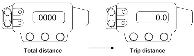
The multi-function display has two buttons, a mode button and a reset button for certain functions.
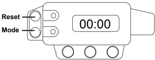
The initial display is the clock (time) screen; if you press mode the display changes in the following order:
- Clock/timer.
- Speed (Km/h or Miles/hour according to the program).
- Total distance in kmh or miles. This has a memory even if battery disconnected.
- Trip distance (can be reset).
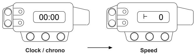
(The Mode button is used to change screens.)
Setting the time
To set the time go to the clock / timer screen and hold in the mode button until the time set screen appears, Reset can be used to change the hours, the pressing Mode once more will allow the minutes to be set also using the Reset button. Once the time is set then the button mode will begin the clock at zero seconds of the minute chosen, this can be useful to coordinate times (ex: in enduro racing).
Chronometer
If we want to use the chronometer then press Reset to put it to zero. Counting begins immediately.
The Trip distance in Km or Miles can be reset by pressing the Reset button.
Trip distance in Km
To program the trip distance in Km or Miles. Once the battery is connected the display indicates that the program is active (metric or imperial). To make the change connect the battery while holding in one of the buttons, the change will appear on the screen. This function remains completely in memory even though the battery may not be connected.
Clock precision
The clock precision can be adjusted if it is fast or slow.
Wheel design
The design of the wheel may change (21"). This affects the precision of the speed and distance measurements.
Backlight
The backlight has an independent circuit powered by 8 to 18 volts AC or DC. The circuit is protected.
FAULT DIAGNOSIS
NOTE
This is not an exhaustive list, it is meant simply as a rough guide to assist troubleshooting for some of the more common difficulties.
| FAULT | CAUSE | SOLUTION | |
| 1 | The starter motor does not work | - The fuse for the starter relay is blown. - Battery discharged. - Low temperature. | - Remove the number plate on the right hand side and the air filter cover then change the starter motor fuse. - Recharge the battery and investigate the causes for discharging, visit a qualified workshop. - Start engine with start pedal. |
| 2 | The engine does not rotate | - Crankshaft locked. - Cylinder/ piston/ crankpin journal seizure. - Transmission assembly seizure. | - Go to a specialist workshop. - Go to a specialist workshop. - Go to a specialist workshop. |
| 3 | Engine rotates but does not start | - Fuel supply incorrect. - The motorcycle has been out of operation for a longer period of time. - Spark plug soiled or humid. - Engine flooded. | - Check fuel pump relay; check fuel pump filter, located in the fuel tank, isn't blocked. - It is advisable to drain the old fuel from the tank. - When the fuel tank is filled with new flammable fuel the engine starts immediately. - Take the spark plug out and replace it. - To «unflood» the engine, full throttle, then operate the kick-start 5 to 10 times or operate the electric starter 2 times in 5 seconds. Then start the engine as described below. If the engine fails to start, unscrew the spark plug and dry it. |
| 3 | Engine rotates but does not start | The ECU pin connector, generator or coil oxidised or in bad condition. - Petrol / gas mixture incorrect (Trim Epprom). | - Remove the seat and the fuel tank, clean the pin connector and treat it using a contact spray. - Clean the petrol tank ventilation. Adjust the throttle body by-pass. Adjust the air filter conduit. |
| 4 | The engine starts but does not stop | - Air supply incorrect. - Fuel insufficient. | - Close the starter. Clean the petrol tank ventilation. Adjust the injector mounting. Adjust the air filter conduit. - Fill the fuel tank with fuel. |
| 5 | The engine overheats | - Insufficient coolant in the circuit. - The radiator is soiled or partially obstructed. | - Add coolant, verify the cooling system seal. - Clean the radiator fins or change it. |
| 6 | The engine does not run smoothly | - Injection system maladjustment. (Trim Epprom). - Valve adjustment incorrect. | - Adjust the injection system. Go to a specialist workshop. - Adjust the valve play. Go to a specialist workshop. - Clean and check fuel system. |
| 7 | The engine is under powerful or accelerates badly. | - Fuel supply faulty. - Air filter obstruction. - Exhaust deteriorated with leaks. - Valve set too small. - Decompression maladjusted. | - Clean or change the air filter. - Check if the exhaust system is damaged, change the glass fibre in the silencer if necessary. - Adjust the valve play. Go to a specialist workshop. - Verify the operation of the system. |
| 8 | High oil consumption | - Piston-cylinder ring diameter tolerance excessive. | - Adjust the tolerance by changing the piston rings. |
| 8 | High oil consumption | - There is too much engine oil. - The quality or viscosity of the oil is insufficient. | - Correct the engine oil level. Drain oil as necessary from the engine. - Empty the engine oil and fill with oil of the recommended viscosity. |
| 9 | Abnormal engine noise | - Ignition problems. - Valve adjustment play. - Over heating. | - Go to a specialist workshop. - Adjust the valve play. Go to a specialist workshop. - See chapter 5. |
| 10 | Detonations in the exhaust | - Carbon in combustion chamber. - Injection system maladjustment. (Trim Epprom). - Incorrect or poor gasoline or wrong octane rating. - Incorrect or non-specified spark plug. - Exhaust system joints deteriorated. | - Clean the combustion chamber. - Go to a specialist workshop. - Drain the petrol and fill with fresh or higher octane petrol. - Change spark plug for a new one or recommended one. - Check if the exhaust system is deteriorated. The seals must be in perfect condition, if not then they must be changed for new ones. |
| 11 | White fumes from the exhaust | - Cylinder head gasket leak (water leaking into cylinder). | - Change the cylinder head gasket. Go to a specialist workshop. |
| 12 | Brown fumes from the exhaust | - Air filter obstruction. | - Clean or change the air filter. Go to a specialist workshop. |
| 13 | The gears do not engage | - Clutch does not release. - Shift fork worn or locked. - Gear locked in transmission. - Shift lever damaged. - Selector position spring broken or loose. | - Go to a specialist workshop. - Change the gear fork. - Go to a specialist workshop. - Change the gear lever. - Adjust the selector position spring or change it. |
| 13 | Gears don't engage | - The spring of the selector is broken. - Cylinder change if broken. - Gear ratchet spring broken. | - Replace the down selector mechanism spring. - Replace the gear drum. - Replace the ratchet spring of the selector. |
| 14 | Gears jump | - Gear change fork damaged in the gears. - Gear teeth worn. - Gear nipple damaged. - Groove gear drum worn. - Gear change fork pivot worn. | - Change gear fork. - Change. Go to a specialist workshop. - Change. Go to a specialist workshop. - Change. Go to a specialist workshop. - Change shaft. Go to a specialist workshop. |
| 15 | Clutch slipping | - No play in the clutch handle. - Clutch plate worn. - Clutch housing worn. - Clutch spring broken or weak. - Clutch plates worn. | - Go to a specialist workshop. - Replace the clutch plate. Go to a specialist workshop. - Replace the clutch hub. - Adjust the selector position spring or change it. - Change the clutch disks. Go to a specialist workshop. |
| 16 | Bike unstable | - Cable obstracts handlebars. - Steering shaft nut too tight. - Steering bearings damaged or worn. - Steering shaft bent. | - Put the cable to one side and release it a little. - Undo the steering shaft nut. - Replace the steering bearing. - Change the steering shaft. Go to a specialist workshop |
| 17 | Shock absorption too hard | - Front forks excess oil. - Front fork oil viscosity too high. - Front forks twisted. - Excessive tyre pressure. | - Eliminate the excess oil to an adequate level. - Empty the fork oil and fill with oil of the recommended viscosity. - Change front fork. Go to a specialist workshop. - Verify tyre pressure. |
| 17 | Shock absorption too hard | - Rear shock badly adjusted | - Adjust the rear shock. |
| 18 | Shock absorption too soft | - Front forks low oil. - Front fork oil viscosity too low. - Front forks twisted. - Low tyre pressure. - Rear shock absorber maladjusted. | - Add oil to the forks as required. - Empty the fork oil and fill with oil of the recommended viscosity. - Change front fork. Go to a specialist workshop. - Verify tyre pressure. - Adjust the rear shock. |
| 19 | The bike makes unusual noise | - Drive chain incorrectly adjusted. - Chain worn. - Rear sprocket worn. - Chain lubrication insufficient. - Rear wheel misaligned. - Oil front fork insufficient. - Front fork spring weak or broken. - Brake disk worn. - Brake pads incorrect position or crystallised. - Cylinder damage. - Brackets, nuts, bolts not properly tightened. | - Adjust the chain. - Change the chain, rear sprocket and secondary transmission pinion. - Change the rear sprocket. - Lubricate using a correct chain lubricant. - Align the rear wheel. Go to a specialist workshop. - Add oil to the forks as required. - Replace the front fork spring. - Replace the brake disk. - Refit the pads or change them. - Replace the damaged cylinder. - Verify and adjust to the correct tightening torques. |
| 20 | Handlebar shakes or excessively vibrates | - Tyre worn, swing arm or needle bearing worn. - Rim off-centre. - Rear wheel misaligned. - Steering shaft play. - Handlebar bracket loose, steering shaft bolt loose. | - Change worn parts. - Centre the rim. - Verify the tension of the wheel spokes. Re-adjust if necessary. - Check the distance between steering shafts and adjust if necessary. - Tighten the handlebar bracket and the steering shaft bolt to the correct tightening torques. |
| 21 | Motorcycle pulls to one side | - Chassis twisted. - Steering incorrectly adjusted. - Steering shaft bent. - Front forks twisted. - Rear wheel misaligned. | - Change the chassis. Go to a specialist workshop. - Adjust the steering. Go to a specialist workshop. - Change steering shaft. Go to a specialist workshop. - Change front fork. - Align the wheels. |
| 22 | The brakes do not function correctly | - Disk worn. - Loss of brake fluid. - Brake fluid deteriorated. - Piston cylinder broken. - Brakes incorrectly adjusted. | - Change disk. - Check the brake circuits. Change those that are damaged or broken. - Drain the brake fluid and put a new product, recommended by the maker. - Replace the piston cylinder. - Adjust the brakes. |
| 23 | The lights blow | - Voltage regulator faulty. | - Remove the seat and the fuel tank then check connections, verify, the voltage regulator and the fuses in the fuse box. |
| 24 | The lighting system does not work | - Installation fuse is blown. | - Remove the back light cover. |
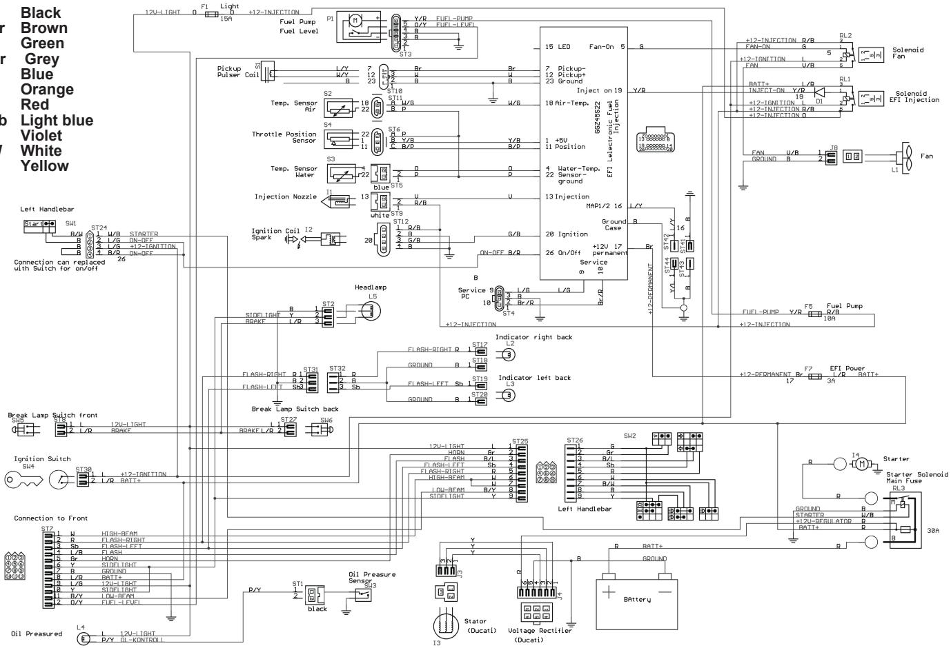
ELECTRIC SCHEMAS
B Black
Br Brown
G Green
Gr Grey
L Blue
Orange
Red
Sb Light blue
Violet
W White
Y Yellow

B Black
Br Brown
G Green
Gr Grey
L Blue
Orange
Red
Sb Light blue
Violet
W White
Y Yellow
WARRANTY TERMS AND CONDITIONS
(According to Law decree 23/2003 on the 10th of July, covering Warranties on Consumer Item Sales)
Warranty terms of the manufacturer GASGAS Motos, S.A.
The company GAS GAS MOTOS, S.A. (hereafter referred to as "GG"), with this present document guarantees the consumer, the purchaser of a vehicle manufactured by GG, that both the materials and the manufacturing are free of defects in accordance with the highest standards of quality. Consequently, GG with this document guarantees the consumer (hereafter referred to as the "purchaser"), in accordance with the conditions set out below, the repair, free of charge, of any defect in materials or that might result from faulty manufacture that is detected in a new motorcycle within the period covered by this Warranty and with no limit on the number of kilometres covered or hours of use.
Warranty Period
The period covered by this Warranty will begin on the day of delivery of the vehicle to the purchaser by a GG authorised dealer, or in the case of demonstration models, on the date in which the vehicle is used for the first time. The seller will be responsible for any unwarranted faults that become apparent within the period established in the Law decree 23/2003 on the 10th of July covering Warranties on Consumer Goods Sold from the time of delivery and in accordance with the Directive 1999/44/EC for other members of the European Community. For countries outside the European Community, the Warranty Period will be determined by the existing regulations in those countries. Nevertheless, should the fault appear during the first six months after the delivery of the motorcycle, it will be presumed that the said fault existed at the time of delivery; from the end of the sixth month onwards, the purchaser must demonstrate that the unwarranted fault existed at the moment of delivery. During the first six months subsequent to the delivery of the repaired vehicle, the seller will be responsible for any unwarranted faults arising out of the repair.
Any defects detected in the product must be brought to the attention of a GG authorised dealer within the Warranty Period. If the last day of this period is a Sunday or an official holiday, the Warranty period will be extended such that the last day of the period covered will be the first working day after the Sunday or official holiday.
Those claims under Warranty for defects not brought to the attention of a GG authorised dealer before the end of the Warranty Period will be excluded.
Obligation of the purchaser
GG will have the right to reject any claims under Warranty in the event that:
a) The purchaser has failed to submit the vehicle to any of the inspections and/or maintenance work required in the Users' Manual, or has exceeded the date set for such inspections or maintenance work. Also excluded from guarantee are those faults that appeared prior to the dates established for an inspection or maintenance work where the latter was not carried out, or was carried out later than the date established.
b) An inspection, maintenance or repair has been performed on the vehicle by third parties not recognised or authorised by GG.
c) Any maintenance or repair has been carried out on the vehicle that violates the technical requirements, specifications and/or instructions indicated by the manufacturer.
d) Spare parts whose use has not been authorised by GG have been used during the course of maintenance work or repairs to the vehicle, or in the event that the vehicle has been used with fuels, lubricants or other liquids (including, amongst others, cleaning products) that have not been expressly mentioned in the specifications set out in the User's Manual.
e) The vehicle has been altered or modified in any way or fitted with components other than those expressly authorised by GG as accepted components of the vehicle.
f) The vehicle has been stored or transported in a way that is not in accordance to the corresponding technical requirements.
g) The vehicle has been used for special purposes other than ordinary use, such as competition, races or record breaking attempts.
h) The vehicle has been directly or indirectly damaged as a result of a fall or an accident.
Warranty exclusions
The following items are not covered by this Warranty:
a) Worn parts, including, without any limitation, spark plugs, batteries, petrol filters, oil filter elements, (secondary) chains, engine output pinions, rear sprockets, air filters, brake discs, brake pads, clutch plates and discs, bulbs, fuses, carbon brushes, footrest rubbers, tyres, inner tubes, cables and other rubber components
b) Lubricants (for example, oil, grease, etc.) and working fluids (for example, battery liquid, coolant, etc.)
c) Inspection, adjustments and other maintenance tasks, as well as all kinds of cleaning work
d) Damage to the paint-work and consequent corrosion due to external causes, such as stones, salt, industrial fumes and other environmental impact, or inadequate cleaning with inappropriate products
e) Any damages caused as a result of the defects, as well as any expenses incurred either directly or indirectly as a consequence of the defects (for example, communication costs, accommodation expenses, car hire costs, public transport costs, breakdown truck fees,, courier costs, etc.), as well as other financial losses (for example, those caused by the loss of the use of the vehicle, loss of income, time lost, etc.)
f) Any acoustic or aesthetic phenomenon that does not significantly affect the condition or use of the motorcycle (for example, small or hidden imperfections, noise or vibrations that are normal in use, etc.)
g) Phenomena that are the result of the ageing of the vehicle (for example, discolouring of painted or metallic coated surfaces).
Various
1.- GG shall have the prerogative to decide, at its own discretion, whether to repair or replace defective parts. Where parts are replaced, ownership of the parts removed shall pass to GG without any other consideration. The GG authorised dealer, to whom the making good of the defects has been entrusted, is not authorised to make any declarations that are binding on GG.
2. In case of doubt regarding the existence of a defect, or a visual or material inspection is required, GG reserves the right to demand the return of the parts which are the object of a claim under Warranty, or to arrange an inspection of the defect by an expert from GG. Any additional obligations arising out of guarantees on parts replaced free of charge, or any other service rendered free of charge, are excluded from the effects of this present warranty. The Warranty on parts replaced within the Warranty Period will end at the expiry date for the Warranty Period of the product concerned.
3.- Should it prove to be the case that a defect can not be repaired, the purchaser guaranteed shall have the right to the cancellation of the contract (payment of compensation) or a partial refund of the purchase price (discount), instead of repairing the motorcycle.
4.- Any claims against Warranty by the purchaser under the terms of the sale contract with the corresponding authorised dealer shall not be affected by the terms of this present Warranty. Neither will this present Warranty affect those additional contractual rights acquired by the purchaser under the general commercial terms and conditions of the authorised dealer. However, such additional rights may only be exercised through claims against the authorised dealer.
5.- Should the purchaser resell the product within the Warranty Period, the duration and conditions of the present Warranty will remain unaltered, in such a way as that the rights to make claims under the present Warranty in accordance with the terms and conditions set out in this present document shall be transferred to the new owner of the motorcycle.
6.- In the case of used motorcycles sold by Gas Gas the Warranty Period will be one year from date of delivery of the goods. And in no case shall the consumer request replacement of the goods.
Notes
Notes
RECOMIENDA EL USO DE ACEITE:
RECOMMENDSTHEUSEOFOIL:
RECOMMANDE L'USAGE DE L'HUILE:
CONSIGLIA L'USO D'OLIO:

Global Racing Oil
GAS GAS
FEBRERO/FEBRUARY/FEBRER 2005
